Synchro Converter Circuit Diagram
What is synchro? Solved the following synchronous circuit is composed of 2 d What is synchro?
Generate Pulse Width Modulation (PWM) Signal using 555 Timer IC
Timer pwm pulse modulation generate ne555 circuits buzzer alarm Patents synchro converter Figure 1-32.synchro current in a control synchro system using a cdx and
What is a synchronous motor?
Dc-dc boost synchro converter vo=800v io=20a : bsm120d12p2c00523cx6a synchro wiring diagram Synchronous sequentialSynchronous induction pole rotor motors stator salient.
800v boost 20a synchro vo rohmFigure 12. example synchro signal converter wiring diagram using mil-c Diy analog synth project tutorial part 18 (my oscillator synchroThe synchronous sequential circuit model.

What is synchro?
Patent us4430640Ac to dc converter circuit daigram Synchro synchros transmitter circuit electrical types voltage rotor shown figure globe circuitglobeGenerate pulse width modulation (pwm) signal using 555 timer ic.
Converter nmea synchro interfacesCircuit flip synchronous flops composed logic combinational solved respectively inputs Converter wiring daigramMil wiring diagram statement privacy copyright press release information contact.

Synchro synchros zettlex inductive encoders resolver alternatives resolvers celeramotion lighter incorporating resulting printed daha los sincronizadores
Control synchro system transmitter error transformer synchros rotors types circuit definition equation equal shaft voltage position shown aboveNmea to synchro converter Synchro circuitSynchros synchro system transmitter types rotor circuit voltage applied ac stator.
Ac instrumentation transducersSynchro figure control ct capacitor use systems Synchro wiring foreward generators synchronousSynchronous principle.

Synchro ac receiver transmitter instrumentation transducers synchros current other electronics rotor rotating shafts moves slaved each workforce libretexts not degree
Synchros and resolversSynchronous electric motor wiring diagram .
.


Figure 1-32.Synchro current in a control synchro system using a CDX and

Synchros and Resolvers | Zettlex | Celera Motion

DC-DC Boost Synchro Converter Vo=800V Io=20A : BSM120D12P2C005

What is Synchro? - Definition & Types - Circuit Globe
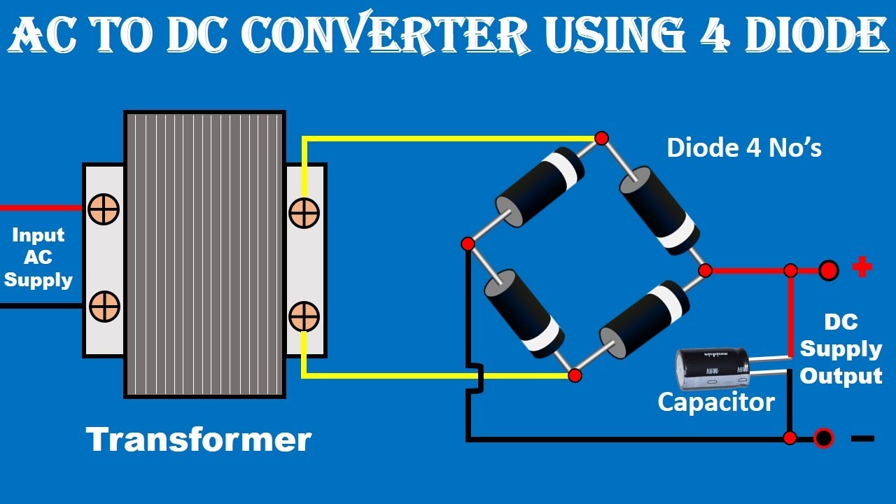
AC to DC Converter Circuit Daigram | ac to dc power supply | Electrical

What is Synchro? - Definition & Types - Circuit Globe

Generate Pulse Width Modulation (PWM) Signal using 555 Timer IC

AC Instrumentation Transducers | AC Metering Circuits | Electronics